Battery-Switchover Circuit Acc
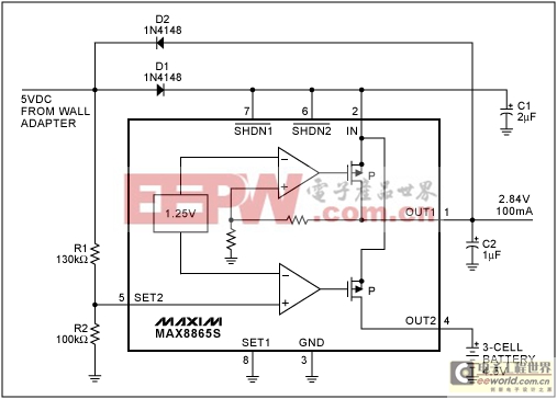
Portable systems often offer the flexibility to operate either from an internal battery or from an ac-to-dc wall adapter. Many such systems include circuitry that switches automatically between the internal battery and an external source as the user connects and disconnects the wall adapter. The circuit shown in Figure 1 implements this idea with a dual linear regulator, one side of which is preset for a 2.84V regulated output. (Other versions of the IC offer 2.8V and 3.15V outputs.)

Figure 1. This linear voltage regulator with automatic-switchover circuitry maintains a 2.84V regulated output as you connect and disconnect the wall-adapter voltage.
The other side of the dual regulator is configured to allow user-adjustable outputs, and in this case monitors the wall-adapter voltage. When you remove that voltage by unplugging the adapter, the regulator's pass transistor routes battery current into the IC to support the 2.84V output. (Current flow in this transistor is counter to that of most applications.) The input bypass capacitor (C1) provides enough holdup time for seamless transitions between the battery and adapter voltages.
Resistors R1 and R2 sense the wall-adapter voltage and determine the switchover threshold (VSW):

Diode D1 isolates the wall-adapter voltage so the battery cannot cause limit cycling by retriggering the switchover. D2 holds the IC's Dual Mode? input in external-feedback mode by maintaining a minimum voltage at the SET2 input.
Battery operation interposes two pass transistors in series between the battery and the regulated output, doubling the regulator's dropout voltage. These transistors each have about 1.1Ω on-resistance. To prevent battery current from bleeding through the OUT2 transistor's intrinsic body diode when operating from the wall adapter, the wall-adapter voltage should be equal to or greater than the maximum battery voltage.
If you turn the regulators on and off with the shutdown inputs active-low SHDN1 and active-low SHDN2, choose the MAX8865 rather than the MAX8866, whose auto-discharge feature will attempt to discharge the battery. As shown, the MAX8865S with a 5V wall adapter and 3-cell battery provides up to 100mA at 2.84V.
A similar idea appeared in the February 3, 1997 issue of Electronic Design.


評(píng)論