NXPUBA2016A35WTL5高效熒光燈電源解決方案
NXP公司的UBA2016A/15/15A 是具有PFC,線性調(diào)光和升壓功能的600V熒光燈驅(qū)動(dòng)器.IC包含了熒光燈控制模塊,半橋驅(qū)動(dòng)器,內(nèi)置了臨界導(dǎo)電模式PFC控制器/驅(qū)動(dòng)器和多種保護(hù)機(jī)制,電源電壓高達(dá)600V,火線電壓高達(dá)390V.本文介紹了UBA2016A/15/15A主要特性和優(yōu)勢(shì),方框圖, 基本的PFC應(yīng)用框圖以及多種TL或CFL應(yīng)用電路, 參考設(shè)計(jì)(230VAC)板指標(biāo),框圖,電路圖,材料清單,PCB布局圖與TL5燈連接電路圖.
UBA2016A/15/15A:600 V fluorescent lamp driver with PFC, linear dimming and boost function
The UBA2016A/15/15A are high voltage Integrated Circuits (IC) intended to drive fluorescent lamps with filaments such as Tube Lamps (TL) and Compact Fluorescent Lamps (CFL) in general lighting applications. The IC comprises a fluorescent lamp control module, half-bridge driver, built-in critical conduction mode Power Factor Correction (PFC) controller/driver and several protection mechanisms. The IC drives fluorescent lamp(s) using a half-bridge circuit made of two MOSFETs with a supply voltage of up to 600 V.
The UBA2016A/15/15A are designed to be supplied by a start-up bleeder resistor and a dV/dt supply from the half-bridge circuit, or any other auxiliary supply derived from the half-bridge or the PFC. The supply current of the IC is low. An internal clamp limits the supply voltage.
UBA2016A/15/15A主要特性:
? Power factor correction features:
? Integrated 4-pin critical conduction mode PFC controller/driver
? Open and short pin-short protection on PFC feedback pin
? Overcurrent protection
? Overvoltage protection
? Half-bridge driver features:
? Integrated level-shifter for the high-side driver of the half-bridge
? Integrated bootstrap diode for the high-side driver supply of the half-bridge
? Independent non-overlap time
? Fluorescent lamp controller features:
? Linear dimming (UBA2016A and UBA2015A only)
? EOL (End-Of-Life) detection (both symmetrical and asymmetrical)
? Adjustable preheat time
? Adjustable preheat current
? Adjustable fixed frequency preheat (UBA2015 and UBA2015A only)
? Lamp ignition failure detection
? Ignition detection of all lamps at multiple lamps with separate resonant tanks
? Second ignition attempt if first failed
? Constant output power independent of mains voltage variations
? Automatic restart after changing lamps
? Adjustable lamp current boost at start-up (UBA2016A only)
? Lamp current control
? Enable input (UBA2015 and UBA2015A only)
? Protection
? Hard switching/capacitive mode protection
? Half-bridge overcurrent (coil saturation) protection
? Lamp overvoltage (lamp removal) protection
? Temperature protection
UBA2016A/15/15A應(yīng)用:
Intended for fluorescent lamp ballasts with either a dimmable (UBA2016A and UBA2015A) or a fixed (UBA2015) output and PFC for AC mains voltages of up to 390 V.
圖1.UBA2016A方框圖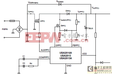
圖2.UBA2016A基本的PFC應(yīng)用框圖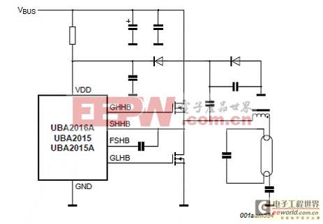
圖3.UBA2016A基本的半橋和IC電源連接圖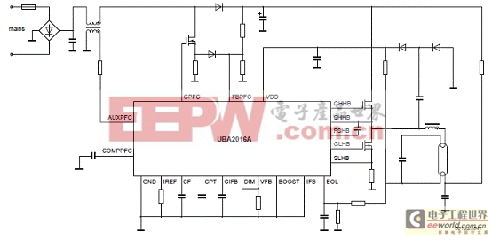
圖4.采用UBA2016A的TL或CFL熒光燈應(yīng)用電路圖(火線濾波器未顯示)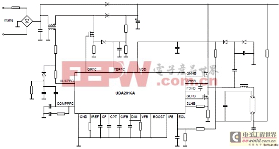
圖5.采用UBA2016A的TL或CFL熒光燈應(yīng)用電路圖(有較好PFC性能,火線濾波器未顯示)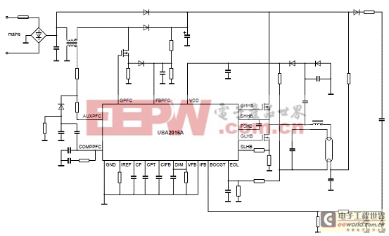
圖6.采用UBA2016A帶固定時(shí)間起動(dòng)的TL或CFL熒光燈應(yīng)用電路圖(火線濾波器未顯示)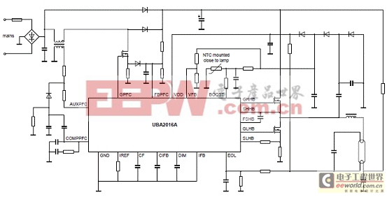
圖7.采用UBA2016A取決于燈溫度起動(dòng)T的L或CFL熒光燈應(yīng)用電路圖(火線濾波器未顯示)
圖8.采用UBA2016A可調(diào)光TL熒光燈應(yīng)用電路圖(火線濾波器未顯示)
UBA2015P參考設(shè)計(jì)(230VAC)
This document describes the specification and use of the UBA2015P board. This reference ballast design is intended to drive two TL5HE28W or TL5HE35W lamps.
The board needs to be connected to the mains voltage. Touching the board while it is connected to the mains voltage must be avoided at all times. An isolated housing is obligatory when used in uncontrolled, non laboratory environments. Galvanic isolation of the mains phase using a variable transformer is always recommended.
圖9.UBA2015P參考設(shè)計(jì)(230VAC)板外形圖
參考設(shè)計(jì)(230VAC)板指標(biāo):
參考設(shè)計(jì)(230VAC)板支持的燈:
The input section includes:
? The fuse
? Surge protection against fast AC transients
? ElectroMagnetic Interference (EMI) filter
? Full-wave rectifier
? Preconditioner or Power Factor Correction (PFC)
The output of the PFC connects to a electrolytic buffer capacitor to supply the half-bridge circuit. The lamp connects to the half-bridge circuit. The UBA2015P controller IC controls the PFC and the half-bridge circuit.
The PFC is implemented as an up converter in boundary conduction mode. The resonant circuit is voltage fed by the half-bridge which consists of two N-channel MOSFETs. The resonant circuit includes a transformer for electrode (pre)heating.
圖10.UBA2015P參考設(shè)計(jì)(230VAC)板方框圖
圖11.燈連接電路圖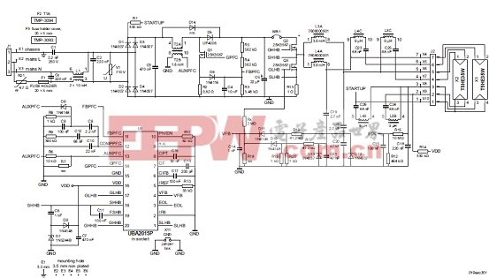
圖12.UBA2015P參考設(shè)計(jì)(230VAC)板電路圖
UBA2015P參考設(shè)計(jì)(230VAC)板材料清單(BOM):


圖13.UBA2015P參考設(shè)計(jì)(230VAC)板PCB布局圖
詳情請(qǐng)見:
http://www.nxp.com/documents/data_sheet/UBA2016A_15_15A.pdf
和
http://www.nxp.com/documents/user_manual/UM10466.pdf










評(píng)論